Installing DCC into the USA Trains GP30
Introduction
USA Trains
of Malden, Massachusetts, USA (a North-Western suburb of Boston MA) are one
of a small number of companies manufacturing G-scale models. They produce a
range of 1:29 scale models of standard gauge equipment for operating on 45mm
track, primarily intended for use on Garden Railways. Late in 2002 they
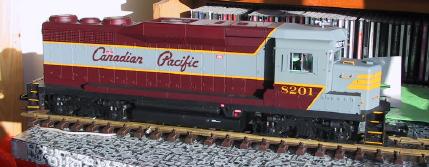
released a new model of the GP30 road/switcher locomotive. The GP30 was a
product of the General Motors Electro-Motive Division (EMD) and was one of
the earlier and smaller examples of what would now be considered a typical
road/switcher diesel locomotive. It's available in a wide range of road names
and running numbers and looks very good indeed. It has two powered twin-axle
trucks, and includes numerous lights and operating smoke.
This page covers
my experiences attempting to fit a DCC decoder inside this model. This is a
pretty difficult locomotive to modify; I certainly found the process long and
frustrating. In particular, although the external detail parts are reasonably
solid, fitting DCC requires digging deep into the inside of the locomotive
where the detail parts are nowhere near as rugged. I broke a number of them
off while performing the modification, and while I'll attempt to warn you of
the pitfalls in this document, I think it would be unwise to assume you'll be
able to do it entirely without breakage.
The decoder I choose to fit to this locomotive was a Lenz LE4024B decoder
which features screw terminals, a 4-amp current rating and four function
outputs. Time will tell whether this will be sufficent, but from what I've
read and test results with a ammeter equiped power supply, I'd say four amps
is an absolute minimum value for this locomotive.
 DISCLAIMER: This modification is hard. You can damage your new
model VERY EASILY with the tools needed to perform the modification. These
instructions are designed to make the process easier, and are based upon one
reasonably successful modification. However
we can accept no liability for what happens to your model, nor do we guarantee
that this modification will work. If you undertake the modification
detailed here, you do so entirely at your own risk. Based upon our experience
some damage to the model is likely.
DISCLAIMER: This modification is hard. You can damage your new
model VERY EASILY with the tools needed to perform the modification. These
instructions are designed to make the process easier, and are based upon one
reasonably successful modification. However
we can accept no liability for what happens to your model, nor do we guarantee
that this modification will work. If you undertake the modification
detailed here, you do so entirely at your own risk. Based upon our experience
some damage to the model is likely.
You will need the following tools to perform the modification (at a
minimum):
- a smallish Philips screwdriver with a long handle
- a pair of thin-nosed pliers
- a pair of wire cutters
- a very sharp knife
- a soldering iron with a fine tip
- a multimeter.
- a DC transformer capable of being set to both low voltages (around 5V)
and higher (around 12V) for testing components independantly.
In addition you will need the following supplies of parts, some of which
may well have to be ordered, in order to modify the locomotive:
- Suitable Heavy Duty (Large Scale) DCC mobile decoder with screw
terminals - the one
used in the illustrations is the Lenz
LE4024B decoder. Those by other makes such as
Digitrax should also work just fine.
Since LGB do not recommend it's solitary use on their own locomotives with
two motor blocks, it would probably be advisable not to use their 55021
decoder with this locomotive, at least as described.
- Fine-grade electrical solder
- Plastic insulating tape
- 6 24volt minature light bulbs - I used LGB part no 68513 (Plug-in bulb,
clear, 24V)
- 6 sets of battery connectors - I used Aristocraft part no ART-29511
battery leads which contain a pair of connectors, one female, one male, each
on a short length of wire.
What Type Of Modification You Want To Do
For some reason, despite the fact it's a very recent design, USA Trains
appear to have given no thought at all to the use of DCC with this model.
In some of the more frustrating moments, I even wondered if they'd deliberately
made it difficult in order to promote sales of their competing Scale Command
system, a promotional video for which is included with the locomotive.
The simple truth is, this is a tough locomotive to modify, at least if you
want to get the most out of it. Much of this is due to how the lights on
the locomotive work. You have basically three possible courses of action:
- Just install DCC for motor control and leave the lights to act only
when the locomotive is moving as they do with DC operation. This is
reasonably easy to do given the right parts, is reversable and should be
quite quick.
- Replace and re-wire the headlights at both ends, and the cab lights
to bring them under DCC control, but do not do anything about the directional
running lights, leaving those to operate as they do in DC operation. This
is the option detailed here.
- Re-wire all lights to work under DCC control - this requires replacing
all eight light bulbs and 4 LEDs, the LEDs with a specialist part that is
hard to obtain. An alternative to this is to fit a rectifier, regulator
and relay circuit to provide suitable power to the existing LEDs.
If you wish to consider this last option, I would recommend reading George
Schreyer's web page on modifying the
GP7/9 for DCC. The issues are basically in common with the GP30.
Your comments and feedback on these instructions would be
appreciated.
Please send feedback to:
Bevis King
Back to DCC Index Page